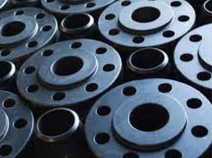
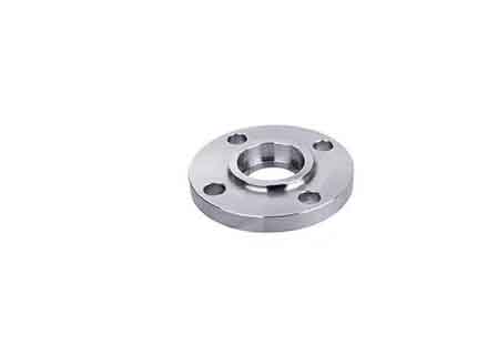
Socket Weld Flange
Overview
At Parmar TechnoForge Pvt. Ltd., we manufacture high-quality Socket Weld Flanges designed to provide strong, leak-proof connections for small-bore high-pressure piping systems. Socket Weld Flanges are ideal for oil & gas, chemical, petrochemical, power, and water treatment industries, allowing easy installation with welded connections and ensuring long-term pipeline integrity.
Our Socket Weld Flanges are precision-forged, heat-treated, and CNC-machined according to ASME B16.5, ASME B16.47, and MSS-SP-44 standards, ensuring dimensional accuracy, mechanical strength, and durability.
Types of Socket Weld Flanges
- 1. Socket Weld Neck Flange – Combines socket weld connection with a weld neck flange for high-pressure applications.
- 2. Socket Weld Slip-On Flange – Provides easy alignment with small-bore pipelines.
- 3. Raised Face (RF) Socket Weld Flange – Enhances gasket seating for leak-proof sealing.
- 4. Flat Face (FF) Socket Weld Flange – Suitable for low-pressure applications.
- 5. Custom Socket Weld Flanges – Manufactured per client drawings or specifications.
Technical Specifications
| Types | SWRF / SWFF |
|---|---|
| Size | 1/2" NB TO 48" NB |
| Class | 150#, 300#, 400#, 600#, 900#, 1500# & 2500# |
| Standards | ASME-B16.5, ASME-B16.47, API-605, MSS-SP-44, DIN/BS |
| Stainless Steel | ASTM A182 F304/ 304L/ 316/ 316L/ 321/ Etc. |
| Carbon Steel | ASTM A105/ A105N/ A350 LF2 Etc. |
| Duplex / Super Duplex | ASTM A182 F51 / F53 / F55 / UNS S31803 / S32750 / S32760 |
| Alloy Steel | ASTM A182 F5/ F9/ F11/ F22/ Etc. |
| Non-Ferrous / Exotic Grades | Monel, Inconel, Hastelloy, Copper Nickel (CuNi10Fe1,6Mn), 70/30 CuNi, DOW Copper, Aluminium Etc. |
Certifications: NACE-MR0175/MR0103, PED / IBR (where applicable)
Customization: All products can be customized as per client
requirements.
Dimensions of CL. 150 Flanges
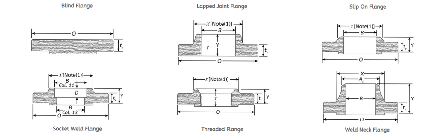
| Nominal Pipe Size | Outside Diameter of Flange O | Thickness of Flange tf | Thickness Lap Joint tf | Diameter of Hub X | Diameter Beginning of Chamfer Welding Neck Ah | Threaded Slip-on Socket Welding Y | Lapped Y | Welding Neck Y | Thread Length Threaded Min. T | Slip-on Socket Welding Min. B | Lapped Min. B | Welding Neck/Socket Welding B | Corner Bore Radius of Lapped Flange and Pipe r | Depth of Socket D |
|---|---|---|---|---|---|---|---|---|---|---|---|---|---|---|
| 1/2 | 3.5 | 0.38 | 0.44 | 1.19 | 0.84 | 0.56 | 0.62 | 1.81 | 0.62 | 0.88 | 0.9 | 0.62 | 0.12 | 0.38 |
| 3/4 | 3.88 | 0.44 | 0.5 | 1.5 | 1.05 | 0.56 | 0.62 | 2 | 0.62 | 1.09 | 1.11 | 0.82 | 0.12 | 0.44 |
| 1 | 4.25 | 0.5 | 0.56 | 1.94 | 1.32 | 0.62 | 0.69 | 2.12 | 0.69 | 1.36 | 1.38 | 1.05 | 0.12 | 0.5 |
| 1 1/4 | 4.62 | 0.56 | 0.62 | 2.31 | 1.66 | 0.75 | 0.81 | 2.19 | 0.81 | 1.7 | 1.72 | 1.38 | 0.19 | 0.56 |
| 1 1/2 | 5 | 0.62 | 0.69 | 2.56 | 1.9 | 0.81 | 0.88 | 2.38 | 0.88 | 1.95 | 1.97 | 1.61 | 0.25 | 0.62 |
| 2 | 6 | 0.69 | 0.75 | 3.06 | 2.38 | 0.94 | 1 | 2.44 | 1 | 2.44 | 2.46 | 2.07 | 0.31 | 0.69 |
| 2 1/2 | 7 | 0.81 | 0.88 | 3.56 | 2.88 | 1.06 | 1.12 | 2.69 | 1.12 | 2.94 | 2.97 | 2.47 | 0.31 | 0.75 |
| 3 | 7.5 | 0.88 | 0.94 | 4.25 | 3.5 | 1.12 | 1.19 | 2.69 | 1.19 | 3.57 | 3.6 | 3.07 | 0.38 | ... |
| 3 1/2 | 8.5 | 0.88 | 0.94 | 4.81 | 4 | 1.19 | 1.25 | 2.75 | 1.25 | 4.07 | 4.1 | 3.55 | 0.38 | ... |
| 4 | 9 | 0.88 | 0.94 | 5.31 | 4.5 | 1.25 | 1.31 | 2.94 | 1.31 | 4.57 | 4.6 | 4.03 | 0.44 | ... |
| 5 | 10 | 0.88 | 0.94 | 6.44 | 5.56 | 1.38 | 1.44 | 3.44 | 1.44 | 5.66 | 5.69 | 5.05 | 0.44 | ... |
| 6 | 11 | 0.94 | 1 | 7.56 | 6.63 | 1.5 | 1.56 | 3.44 | 1.56 | 6.72 | 6.75 | 6.07 | 0.5 | ... |
| 8 | 13.5 | 1.06 | 1.12 | 9.69 | 8.63 | 1.69 | 1.75 | 3.94 | 1.75 | 8.72 | 8.75 | 7.98 | 0.5 | ... |
| 10 | 16 | 1.12 | 1.19 | 12 | 10.75 | 1.88 | 1.94 | 3.94 | 1.94 | 10.88 | 10.92 | 10.02 | 0.5 | ... |
| 12 | 19 | 1.19 | 1.25 | 14.38 | 12.75 | 2.12 | 2.19 | 4.44 | 2.19 | 12.88 | 12.92 | 12 | 0.5 | ... |
| 14 | 21 | 1.31 | 1.38 | 15.75 | 14 | 2.19 | 3.12 | 4.94 | 2.25 | 14.14 | 14.18 | 0.5 | ... | |
| 16 | 23.5 | 1.38 | 1.44 | 18 | 16 | 2.44 | 3.44 | 4.94 | 2.5 | 16.16 | 16.19 | 0.5 | ... | |
| 18 | 25 | 1.5 | 1.56 | 19.88 | 18 | 2.62 | 3.81 | 5.44 | 2.69 | 18.18 | 18.2 | 0.5 | ... | |
| 20 | 27.5 | 1.62 | 1.69 | 22 | 20 | 2.81 | 4.06 | 5.62 | 2.88 | 20.2 | 20.25 | 0.5 | ... | |
| 24 | 32 | 1.81 | 1.88 | 26.12 | 24 | 3.19 | 4.38 | 5.94 | 3.25 | 24.25 | 24.25 | 0.5 | ... |
Note: (1) This dimension is for the large end of the hub, which may be straight or tapered. Taper shall not exceed 7° on threaded, slip-on, and lapped flanges.
Dimensions of CL. 300 Flanges
| DIMENSIONS OF CL. 300 FLANGES | |||||||||||||||
|---|---|---|---|---|---|---|---|---|---|---|---|---|---|---|---|
| Nominal Pipe Size | Outside Diameter of Flange (O) | Thickness of Flange Min. (tf) | Thickness Lap Joint Min. (t) | Diameter of Hub (X) | Diameter Beginning of Chamfer Welding Neck (Ah) | Threaded / Slip-on / Socket Welding (Y) | Lapped (Y) | Welding Neck (Y) | Thread Length Threaded Min. (T) | Slip-on Socket Welding Min. (B) | Lapped Min. (B) | Welding Neck / Socket Welding (B) | Corner Bore Radius of Flange and Pipe (r) | Counter-bore Threaded Flange Min. (Q) | Depth of Socket (D) |
| 1/2 | 3.75 | 0.5 | 0.56 | 1.5 | 0.84 | 0.81 | 0.88 | 2 | 0.62 | 0.88 | 0.9 | 0.62 | 0.12 | 0.93 | 0.38 |
| 3/4 | 4.62 | 0.56 | 0.62 | 1.88 | 1.05 | 0.94 | 1 | 2.19 | 0.62 | 1.09 | 1.11 | 0.82 | 0.12 | 1.14 | 0.44 |
| 1 | 4.88 | 0.62 | 0.69 | 2.12 | 1.32 | 1 | 1.06 | 2.38 | 0.69 | 1.36 | 1.38 | 1.05 | 0.12 | 1.41 | 1/2 |
| 1 1/4 | 5.25 | 0.69 | 0.75 | 2.5 | 1.66 | 1 | 1.06 | 2.5 | 0.81 | 1.7 | 1.72 | 1.38 | 0.19 | 1.75 | 5/9 |
| 1 1/2 | 6.12 | 0.75 | 0.81 | 2.75 | 1.9 | 1.13 | 1.19 | 2.63 | 0.88 | 1.95 | 1.97 | 1.61 | 0.25 | 1.98 | 5/8 |
| 2 | 6.5 | 0.81 | 0.88 | 3.31 | 2.38 | 1.25 | 1.31 | 2.69 | 1.12 | 2.44 | 2.46 | 2.07 | 0.31 | 2.5 | 2/3 |
| 2 1/2 | 7.5 | 0.94 | 1 | 3.94 | 2.88 | 1.44 | 1.5 | 2.94 | 1.25 | 2.94 | 2.97 | 2.47 | 0.31 | 3 | 3/4 |
| 3 | 8.25 | 1.06 | 1.12 | 4.62 | 3.5 | 1.63 | 1.69 | 3.06 | 1.25 | 3.57 | 3.6 | 3.07 | 0.38 | 3.63 | 4/5 |
| 3 1/2 | 9 | 1.12 | 1.19 | 5.25 | 4 | 1.69 | 1.75 | 3.13 | 1.44 | 4.07 | 4.1 | 3.55 | 0.38 | 4.13 | – |
| 4 | 10 | 1.19 | 1.25 | 5.75 | 4.5 | 1.82 | 1.88 | 3.32 | 1.44 | 4.57 | 4.6 | 4.03 | 0.44 | 4.63 | – |
| 5 | 11 | 1.31 | 1.38 | 7 | 5.56 | 1.94 | 2 | 3.82 | 1.69 | 5.66 | 5.69 | 5.05 | 0.44 | 5.69 | – |
| 6 | 12.5 | 1.38 | 1.44 | 8.12 | 6.63 | 2 | 2.06 | 3.82 | 1.81 | 6.72 | 6.75 | 6.07 | 0.5 | 6.75 | – |
| 8 | 15 | 1.56 | 1.62 | 10.25 | 8.63 | 2.38 | 2.44 | 4.32 | 2 | 8.72 | 8.75 | 7.98 | 0.5 | 8.75 | – |
| 10 | 17.5 | 1.81 | 1.88 | 12.62 | 10.75 | 2.56 | 3.75 | 4.56 | 2.19 | 10.88 | 10.92 | 10.02 | 0.5 | 10.88 | – |
| 12 | 20.5 | 1.94 | 2 | 14.75 | 12.75 | 2.82 | 4 | 5.06 | 2.38 | 12.88 | 12.92 | 12 | 0.5 | 12.94 | – |
| 14 | 23 | 2.06 | 2.12 | 16.75 | 14 | 2.94 | 4.38 | 5.56 | 2.5 | 14.14 | 14.18 | – | 0.5 | 14.19 | – |
| 16 | 25.5 | 2.19 | 2.25 | 19 | 16 | 3.19 | 4.75 | 5.69 | 2.69 | 16.16 | 16.19 | – | 0.5 | 16.19 | – |
| 18 | 28 | 2.31 | 2.38 | 21 | 18 | 3.44 | 5.12 | 6.19 | 2.75 | 18.18 | 18.2 | – | 0.5 | 18.19 | – |
| 20 | 30.5 | 2.44 | 2.5 | 23.12 | 20 | 3.69 | 5.5 | 6.32 | 2.88 | 20.2 | 20.25 | – | 0.5 | 20.19 | – |
| 24 | 36 | 2.69 | 2.75 | 27.62 | 24 | 4.13 | 6 | 6.56 | 3.25 | 24.25 | 24.25 | – | 0.5 | 24.19 | – |
Note: (1) This dimension is for the large end of the hub, which may be straight or tapered. Taper shall not exceed 7° on threaded, slip-on, and lapped flanges.
Dimensions of CL. 600 Flanges
| DIMENSIONS OF CL. 600 FLANGES | ||||||||||||||
|---|---|---|---|---|---|---|---|---|---|---|---|---|---|---|
| Nominal Pipe Size | Outside Diameter of Flange (O) | Thickness of Flange Min. (t) | Diameter of Hub (X) | Hub Dia. Beginning of Chamfer Welding Neck (A) | Length Through Hub Threaded/Slip-on (Y) | Length Through Hub Lapped (Y) | Length Through Hub Welding Neck (Y) | Thread Length Min. (T) | Bore Slip-on Min. (B) | Bore Lapped Min. (B) | Bore Welding Neck (B) | Corner Radius (r) | Counter-bore Threaded Flange (Q) | Depth of Socket (D) |
| 1/2 | 3.75 | 0.56 | 1.50 | 0.84 | 0.88 | 0.88 | 2.06 | 0.62 | 0.88 | 0.90 | To Be Specified By Purchaser | 0.12 | 0.93 | 0.38 |
| 3/4 | 4.62 | 0.62 | 1.88 | 1.05 | 1.00 | 1.00 | 2.25 | 0.62 | 1.09 | 1.11 | 0.12 | 1.14 | 0.44 | |
| 1 | 4.88 | 0.69 | 2.12 | 1.32 | 1.06 | 1.06 | 2.44 | 0.69 | 1.36 | 1.38 | 0.12 | 1.41 | 0.50 | |
| 1 1/4 | 5.25 | 0.81 | 2.50 | 1.66 | 1.12 | 1.12 | 2.62 | 0.81 | 1.70 | 1.72 | 0.19 | 1.75 | 0.56 | |
| 1 1/2 | 6.12 | 0.88 | 2.75 | 1.90 | 1.25 | 1.25 | 2.75 | 0.88 | 1.95 | 1.97 | 0.25 | 1.99 | 0.62 | |
| 2 | 6.50 | 1.00 | 3.31 | 2.38 | 1.44 | 1.44 | 2.88 | 1.12 | 2.44 | 2.46 | 0.31 | 2.50 | 0.69 | |
| 2 1/2 | 7.50 | 1.12 | 3.94 | 2.88 | 1.62 | 1.62 | 3.12 | 1.25 | 2.94 | 2.97 | 0.31 | 3.00 | 0.75 | |
| 3 | 8.25 | 1.25 | 4.62 | 3.50 | 1.81 | 1.81 | 3.25 | 1.38 | 3.57 | 3.60 | 0.38 | 3.63 | 0.81 | |
| 3 1/2 | 9.00 | 1.38 | 5.25 | 4.00 | 1.94 | 1.94 | 3.38 | 1.56 | 4.07 | 4.10 | 0.38 | 4.13 | ||
| 4 | 10.75 | 1.50 | 6.00 | 4.50 | 2.12 | 2.12 | 4.00 | 1.62 | 4.57 | 4.60 | 0.44 | 4.63 | ||
| 5 | 13.00 | 1.75 | 7.44 | 5.56 | 2.38 | 2.38 | 4.50 | 1.88 | 5.66 | 5.69 | 0.44 | 5.69 | ||
| 6 | 14.00 | 1.88 | 8.75 | 6.63 | 2.62 | 2.62 | 4.62 | 2.00 | 6.72 | 6.75 | 0.50 | 6.75 | ||
| 8 | 16.50 | 2.19 | 10.75 | 8.63 | 3.00 | 3.00 | 5.25 | 2.25 | 8.72 | 8.75 | 0.50 | 8.75 | ||
| 10 | 20.00 | 2.50 | 13.50 | 10.75 | 3.38 | 4.38 | 6.00 | 2.56 | 10.88 | 10.92 | 0.50 | 10.88 | ||
| 12 | 22.00 | 2.62 | 15.75 | 12.75 | 3.62 | 4.62 | 6.12 | 2.75 | 12.88 | 12.92 | 0.50 | 12.94 | ||
| 14 | 23.75 | 2.75 | 17.00 | 14.00 | 3.69 | 5.00 | 6.50 | 2.88 | 14.14 | 14.18 | 0.50 | 14.19 | ||
| 16 | 27.00 | 3.00 | 19.50 | 16.00 | 4.19 | 5.50 | 7.00 | 3.06 | 16.16 | 16.19 | 0.50 | 16.19 | ||
| 18 | 29.25 | 3.25 | 21.50 | 18.00 | 4.62 | 6.00 | 7.25 | 3.12 | 18.18 | 18.20 | 0.50 | 18.19 | ||
| 20 | 32.00 | 3.50 | 24.00 | 20.00 | 5.00 | 6.50 | 7.50 | 3.25 | 20.20 | 20.25 | 0.50 | 20.19 | ||
| 24 | 37.00 | 4.00 | 28.25 | 24.00 | 5.50 | 7.25 | 8.00 | 3.62 | 24.25 | 24.25 | 0.50 | 24.19 | ||
Note: (1) This dimension is for the large end of the hub, which may be straight or tapered. Taper shall not exceed 7° on threaded, slip-on, and lapped flanges.